- 您现在的位置:买卖IC网 > Sheet目录474 > MAX3524EVKIT (Maxim Integrated)EVAL KIT MAX3524
�� �
�
�Low-Noise,� High-Linearity�
�Broadband� Amplifier�
�Table� 1.� Shunt-Resistor� Noise-Figure�
�Values�
�RF� Input� Power� Control� Using� the�
�Operational� Amplifier�
�In� a� cable� system,� the� power� level� at� the� LNA� input� is�
�R� SHUNT� (� ?� )�
�450�
�250�
�125�
�?� S11� ?� (LNA)� (dB)�
�-6�
�-8�
�-10�
�NOISE� FIGURE� (dB)�
�5� to� 5.5�
�5.5� to� 6�
�6� to� 6.5�
�typically� restricted� to� a� maximum� value� to� maintain� lin-�
�earity.� This� is� accomplished� by� connecting� a� variable�
�attenuator� at� the� input� of� the� LNA� and� varying� the� atten-�
�uation� with� the� operational� amplifier� output.� The� opera-�
�tional� amplifier� receives� a� DC� control� input� that� is�
�proportional� to� LNA� output� power.� See� Typical�
�Applications� Information�
�Bias� Current�
�The� resistor,� R� BIAS� ,� connected� between� BIAS� and� GND�
�controls� the� LNA� current.� To� make� the� current� insensi-�
�tive� to� temperature� fluctuations,� select� a� 1%,� low� tem-�
�perature� coefficient� resistor� for� R� BIAS� .� The� current�
�drawn� by� the� LNA� is� calculated� using� the� following� for-�
�mula:�
�I� BIAS� ≈� 0.58V� /� (R� BIAS� +� DC� resistance� of� L� BIAS� )�
�It� is� important� to� include� the� inductor� resistance� in� the�
�above� equation� as� it� is� typically� 1� ?� to� 2� ?� .� The�
�MAX3524� EV� kit� uses� a� nominal� inductor� with� DC� resis-�
�tance� of� 1.4� ?� .� Higher� values� of� R� BIAS� may� be� used� to�
�reduce� supply� current� predominantly� at� the� expense� of�
�linearity.� Circuit� board� layout� and� source� impedance�
�may� require� the� value� of� I� BIAS� to� be� optimized� for� best�
�Application� Circuit� .�
�Layout� Issues�
�A� properly� designed� PC� board� is� essential� to� any�
�RF/microwave� circuit.� Use� short� interconnect� and� con-�
�trolled� impedance� lines� on� all� high-frequency� inputs�
�and� outputs.� Use� low� inductance� connections� to�
�ground� on� all� GND� nodes� and� place� decoupling�
�capacitors� close� to� all� V� CC� connections.� The� EP� is� the�
�ground� for� the� MAX3524� and� must� be� soldered� to�
�ground� for� proper� operation.�
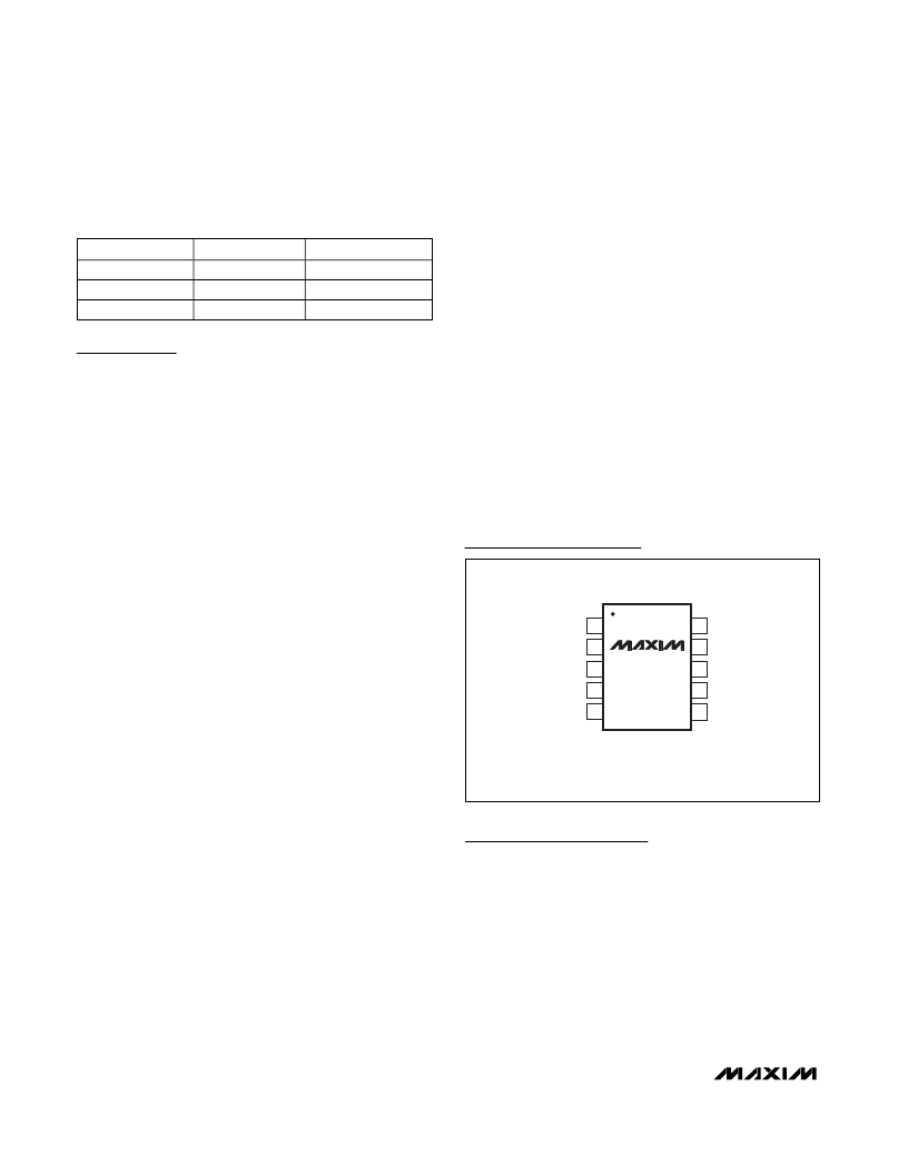
�Pin� Configuration�
�TOP� VIEW�
�linearity.�
�V� CC� 1�
�10� RFOUT+�
�Input� and� Output�
�The� LNA� input� is� single-ended.� The� RF� input� signal� is�
�coupled� to� RFIN� through� a� DC� blocking� capacitor.� The�
�LNA� outputs� drive� a� differential� load,� such� as� a� mixer,�
�through� DC� blocking� capacitors.� The� equivalent� input�
�LNA� impedance� is� 330� ?� resistive� in� parallel� with� 1.8pf,�
�as� shown� in� Figure� 2.� The� approximate� equivalent� dif-�
�ferential� output� impedance� of� the� LNA� is� 60� ?� .� To�
�RFIN�
�RFGND�
�OPOUT�
�OPIN-�
�2�
�3�
�4�
�5�
�MAX3524�
�μ� MAX�
�9�
�8�
�7�
�6�
�V� CC�
�REFOUT-�
�OPIN+�
�BIAS�
�achieve� S11� less� than� -6dB,� an� insertion� loss� of� greater�
�than� 1dB� must� exist� between� the� cable� input� and�
�MAX3524.� This� loss� typically� comes� from� a� diplexer�
�and� PIN� attenuator� in� a� cable� modem� application.� A�
�shunt� resistor� may� be� added� at� the� input� of� the� LNA� to�
�improve� the� return� loss� (S11).� Typically� the� return� loss�
�of� the� system� is� 2dB� better,� as� explained� above.� The�
�S11� and� noise-figure� values� for� different� shunt� resistors�
�are� given� in� Table� 1.�
�TRANSISTOR� COUNT:� 550�
�Chip� Information�
�6�
�_______________________________________________________________________________________�
�发布紧急采购,3分钟左右您将得到回复。
相关PDF资料
MAX3540EVKIT#
KIT FOR MAX3540 DVB TUNER
MAX3541EVKIT+
KIT FOR MAX3541 DVB TUNER
MAX3542CLM+
IC TV TUNER SGL CONV 48LFCGA
MAX3542EVKIT+
KIT FOR MAX3542 DVB TUNER
MAX3543EVKIT+
EVAL KIT MAX3543
MAX3558EVKIT
EVAL KIT MAX3558
MAX4000EUA+T
IC CNTRLR RF-DETECT 8-MSOP
MAX4001EVKIT
EVAL KIT FOR MAX4001
相关代理商/技术参数
MAX352C/D
功能描述:模拟开关 IC RoHS:否 制造商:Texas Instruments 开关数量:2 开关配置:SPDT 开启电阻(最大值):0.1 Ohms 切换电压(最大): 开启时间(最大值): 关闭时间(最大值): 工作电源电压:2.7 V to 4.5 V 最大工作温度:+ 85 C 安装风格:SMD/SMT 封装 / 箱体:DSBGA-16
MAX352CPE
功能描述:模拟开关 IC RoHS:否 制造商:Texas Instruments 开关数量:2 开关配置:SPDT 开启电阻(最大值):0.1 Ohms 切换电压(最大): 开启时间(最大值): 关闭时间(最大值): 工作电源电压:2.7 V to 4.5 V 最大工作温度:+ 85 C 安装风格:SMD/SMT 封装 / 箱体:DSBGA-16
MAX352CPE+
功能描述:模拟开关 IC Precision Quad SPST RoHS:否 制造商:Texas Instruments 开关数量:2 开关配置:SPDT 开启电阻(最大值):0.1 Ohms 切换电压(最大): 开启时间(最大值): 关闭时间(最大值): 工作电源电压:2.7 V to 4.5 V 最大工作温度:+ 85 C 安装风格:SMD/SMT 封装 / 箱体:DSBGA-16
MAX352CSE
功能描述:模拟开关 IC RoHS:否 制造商:Texas Instruments 开关数量:2 开关配置:SPDT 开启电阻(最大值):0.1 Ohms 切换电压(最大): 开启时间(最大值): 关闭时间(最大值): 工作电源电压:2.7 V to 4.5 V 最大工作温度:+ 85 C 安装风格:SMD/SMT 封装 / 箱体:DSBGA-16
MAX352CSE+
功能描述:模拟开关 IC Precision Quad SPST RoHS:否 制造商:Texas Instruments 开关数量:2 开关配置:SPDT 开启电阻(最大值):0.1 Ohms 切换电压(最大): 开启时间(最大值): 关闭时间(最大值): 工作电源电压:2.7 V to 4.5 V 最大工作温度:+ 85 C 安装风格:SMD/SMT 封装 / 箱体:DSBGA-16
MAX352CSE+T
功能描述:模拟开关 IC Precision Quad SPST RoHS:否 制造商:Texas Instruments 开关数量:2 开关配置:SPDT 开启电阻(最大值):0.1 Ohms 切换电压(最大): 开启时间(最大值): 关闭时间(最大值): 工作电源电压:2.7 V to 4.5 V 最大工作温度:+ 85 C 安装风格:SMD/SMT 封装 / 箱体:DSBGA-16
MAX352CSE-T
功能描述:模拟开关 IC RoHS:否 制造商:Texas Instruments 开关数量:2 开关配置:SPDT 开启电阻(最大值):0.1 Ohms 切换电压(最大): 开启时间(最大值): 关闭时间(最大值): 工作电源电压:2.7 V to 4.5 V 最大工作温度:+ 85 C 安装风格:SMD/SMT 封装 / 箱体:DSBGA-16
MAX352EJE
功能描述:模拟开关 IC RoHS:否 制造商:Texas Instruments 开关数量:2 开关配置:SPDT 开启电阻(最大值):0.1 Ohms 切换电压(最大): 开启时间(最大值): 关闭时间(最大值): 工作电源电压:2.7 V to 4.5 V 最大工作温度:+ 85 C 安装风格:SMD/SMT 封装 / 箱体:DSBGA-16